

- Products
-

 Networking
- > Industrial Ethernet
- Industrial PoE Media Converter
- Industrial Media Converter
- Industrial Unmanaged PoE Switch
- Industrial Managed PoE Switch
- Industrial Unmanaged Ethernet Switch
- Industrial Managed Ethernet Switch
- Industrial Serial Fiber Converter
- Industrial PoE Injector
- Industrial PoE Splitter
- Industrial PoE Extender
- Industrial Optical Switch
- DIN-Rail Power Supply
- Rackmount DIN-Rail Bracket
- Industrial Ethernet Switch & 5G Router
- LED Screen Fiber Converter
- > Commercial Ethernet
- > Media Converter
- > Industrial Ethernet
-
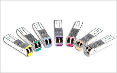 SFP Transceiver
-
 Video Transmission
-
 Other Networking Products
- > Fiber Optic Card & Network Adapter
- > USB over UTP / Fiber Extender
- > DIN Rail Fiber Splice Box
- > Telephone to Fiber Mux
- > Surge Protector
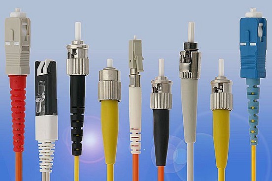
- > Fiber Optic Cable
- > RF over Fiber Transmission
- > Protocol Converter
- > SDH PDH Multiplexer Protocol Converter
- > Fiber Enclosure
- > Power Distribution Unit
- > IP Ethernet over Coax (EOC) Converter
- > Fiber Optic Card & Network Adapter
-
- Solutions
- News
- About
- Contact


 Networking
Industrial PoE Media Converter
Industrial Media Converter
Industrial Unmanaged PoE Switch
Industrial Managed PoE Switch
Industrial Unmanaged Ethernet Switch
Industrial Managed Ethernet Switch
Industrial Serial Fiber Converter
Industrial PoE Injector
Industrial PoE Splitter
Industrial PoE Extender
Industrial Optical Switch
DIN-Rail Power Supply
Rackmount DIN-Rail Bracket
Industrial Ethernet Switch & 5G Router
LED Screen Fiber Converter
SFP TransceiverVideo Transmission
1080P AHD CVI TVI over Fiber Converter
5MP AHD CVI TVI over Fiber Converter
Video Converter Rack
Multi-functional Video Converter
AHD/CVI/TVI Video Multiplexer
Other Networking Products


400GBASE-ER8 QSFP-DD 1310nm 40km Transceiver
Model:LNK-QDD-400G-ER8-40
Ø Compliant with IEEE std 802.3cnTM-2019:
- 400GBASE-ER8 optical interface
- 400GAUI-8 electrical interface
Ø Compliant with QSFP-DD MSA HW Rev 5.1 with duplex LC connector
Ø Compliant with QSFP-DD CMIS Rev 4.0


400GBASE-ER8
QSFP-DD 1310nm 40km Transceiver


