

- Products
-

 Networking
- > Industrial Ethernet
- Industrial PoE Media Converter
- Industrial Media Converter
- Industrial Unmanaged PoE Switch
- Industrial Managed PoE Switch
- Industrial Unmanaged Ethernet Switch
- Industrial Managed Ethernet Switch
- Industrial Serial Fiber Converter
- Industrial PoE Injector
- Industrial PoE Splitter
- Industrial PoE Extender
- Industrial Optical Switch
- DIN-Rail Power Supply
- Rackmount DIN-Rail Bracket
- > Commercial Ethernet
- > Media Converter
- > Industrial Ethernet
-
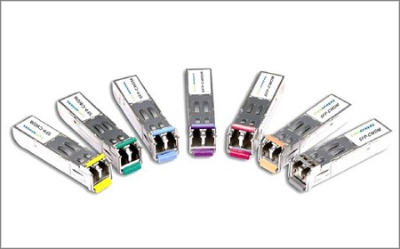 SFP Transceiver
- > Huawei HiSilicon Modules
- > 400G QSFP-DD Transceiver
- > 100G QSFP 28 Transceiver
- > 50G QSFP28 Transceiver
- > 40G QSFP+ Transceiver
- > SFP+ Transceiver
- > XFP Transceiver
- > SFP Transceiver
- > Video SFP Transceiver
- > 1x9 Optical Transceiver
- > RF over Fiber Transmission
- > Telephone to Fiber Mux
- > Protocol Converter
- > SDH PDH Multiplexer Protocol Converter
- > Huawei HiSilicon Modules
-
 Video Transmission
-
 Other Accessories
-
- Solutions
- News
- About
- Contact


 NetworkingSFP TransceiverVideo TransmissionOther Accessories


400GBASE-DR4 QSFP-DD 1310nm 500m Transceiver
Model:LNK-QDD-400G-DR4-05
Ø Compliant with IEEE802.3bs standard:
- 400GAUI-8 electrical interface
Ø Compliant with IEEE 802.3bs standard:
- 400GBASE-DR4 optical interface
Ø Compliant with QSFP-DD MSA HW Rev 5.1
Type 2 housing with MPO-12 connector
Ø Compliant with QSFP-DD CMIS Rev 4.0


400GBASE-DR4 QSFP-DD 1310nm 500m Transceiver
Features
Ø Compliant with IEEE802.3bs standard:
- 400GAUI-8 electrical interface
Ø Compliant with IEEE 802.3bs standard:
- 400GBASE-DR4 optical interface
Ø Compliant with QSFP-DD MSA HW Rev 5.1
Type 2 housing with MPO-12 connector
Ø Compliant with QSFP-DD CMIS Rev 4.0
Ø Supports 3dB channel insertion loss
Ø Maximum power consumption 10W
Ø Case operating temperature 0°C to 70°C
Ø Two wire serial Interface with digital diagnostic monitoring
Ø Complies with EU Directive 2011/65/EU
(RoHS compliant)
Ø Class 1 Laser
Application
► Fiber Channel Switch Infrastructure
► Router/Server interface
► Other optical transmission systems
Transmitter Optical Specifications
|
|
||||||
|
Parameter |
Symbol |
Min. |
Typical |
Max. |
Unit |
Notes |
|
Wavelength |
λC |
1304.5 |
1311 |
1317.5 |
nm |
|
|
Side Mode Suppression Ratio |
SMSR |
30 |
- |
- |
dB |
|
|
Average Launch Power, each lane |
AOPL |
-2.9 |
- |
4.0 |
dBm |
1 |
|
Outer Optical Modulation Amplitude (OMAouter), each lane |
TOMA |
-0.8 |
- |
4.2 |
dBm |
2 |
|
Launch Power in OMAouterminus TDECQ, |
TOMA |
-2.2 |
- |
- |
dBm |
|
|
Transmitter and Dispersion Eye Closure for PAM4 (TDECQ), each lane |
TDECQ |
- |
- |
3.4 |
dB |
|
|
TDECQ – 10log10(Ceq) |
- |
- |
- |
3.4 |
dB |
|
|
Average Launch Power of OFF Transmitter, each lane |
TOFF |
- |
- |
-15 |
dBm |
|
|
Extinction Ratio, each lane |
ER |
3.5 |
- |
- |
dB |
|
|
Transmitter transition time |
- |
- |
- |
17 |
ps |
|
|
RIN21.4OMA |
RIN |
- |
- |
-136 |
dB/Hz |
|
|
Optical Return Loss Tolerance |
ORL |
- |
- |
21.4 |
dB |
|
|
Transmitter Reflectance |
TR |
- |
- |
-26 |
dB |
3 |
Note 1: Average launch power, each lane (min) is informative and not the principal indicator of signal strength
Note 2: Even if TDECQ < 1.4dB, OMAouter(min) must exceed this value
Note 3: Transmitter reflectance is defined looking into the transmitter
Receiver Optical Specifications
|
|
||||||
|
Parameter |
Symbol |
Min. |
Typical |
Max. |
Unit |
Notes |
|
Wavelength |
λC |
1304.5 |
1311 |
1317.5 |
nm |
|
|
Damage Threshold, each lane |
AOPD |
5 |
- |
- |
dBm |
|
|
Average Receive Power, each lane |
AOPR |
-5.9 |
- |
4.0 |
dBm |
1 |
|
Receive Power (OMAouter), each lane |
OMAR |
- |
- |
4.2 |
dBm |
|
|
Receiver Reflectance |
RR |
- |
- |
-26 |
dB |
|
|
Receiver Sensitivity (OMAouter), each lane |
SOMA |
- |
- |
-4.4 |
dBm |
2 |
|
Stressed Receiver Sensitivity (OMAouter), each lane |
SRS |
- |
- |
-1.9 |
dBm |
3 |
|
Conditions of stressed receiver sensitivity test |
|
|
|
|
|
|
|
Stressed eye closure for PAM4 (SECQ) |
|
|
3.4 |
|
dB |
|
|
SECQ – 10log10(Ceq), lane under test |
- |
- |
- |
3.4 |
dB |
|
|
OMAouterof each aggressor lane |
|
|
4.2 |
|
dBm |
|
Note 1: Note 1: Average receive power, (min) is informative and not the principal indicator of signal strength
Note 2: Receiver sensitivity (OMAouter), each lane (max) is informative and is defined for a transmitter with a value of SECQ up to 3.4 dB.
Note 3: Measured with conformance test signal at TP3 for the BER = 2.4x10⁻⁴
- Download FileName:E-link 400G QSFP-DD DR4 1310nm 500m Transceiver Datasheet V1.0.pdf Size: 659KB
Ordering Information
|
|
||||
|
Part No. |
Application |
Data Rate |
Laser Source |
Fiber Type |
|
LNK-QDD-400G-DR4-05 |
400GBASE-DR4 |
400GB Ethernet |
EML |
Single Mode Fiber |


